By Tom Lecklider, Senior Technical Editor, EE, January 2014
Specific application areas were the focus of EMC equipment companies that introduced new products in the last year. One of these—time-based measurements—is a major theme. As discussed in an EE-Evaluation Engineering spectrum monitoring article in November 2013, the amount of time that a conventional spectrum analyzer requires to sweep a given frequency span may be longer than the duration of the transient signal being measured.
FFT-based techniques solve this problem by rapidly acquiring the signal in the time domain. In addition to spectrum monitoring, automotive and lighting applications often have similar constraints.
According to John Zavodny, EMC specialist team manager at Rohde & Schwarz, “The ESRP Pre-Compliance Test Receiver (Figure 1)… offers two methods for measuring disturbance signals: the fast, FFT-based time-domain scan and the traditional—but slower—stepped-frequency scan…. In the time-domain scan mode, the ESRP measures conducted disturbances in the CISPR band B with quasi-peak weighting faster, by many orders of magnitude, than conventional EMI test receivers using the traditional method. The fast time-domain scan mode significantly reduces measurement times. This makes the ESRP ideal for testing DUTs with function-specific short operating times in the automotive and lighting industries, such as starters and window lifters or fluorescent lamps in the warm-up phase,” he concluded.
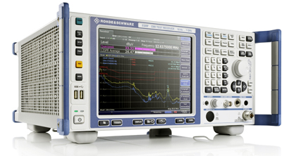
Figure 1. ESRP Pre-Compliance Test Receiver
Courtesy of Rohde & Schwarz
Troubleshooting
Keeping with the time-domain theme, an oscilloscope often is the instrument of choice for EMI sniffing. Near-field probes, such as found in the Model 7405 set of probes sold by ETS-Lindgren, help to locate sources of interference. As explained in the 7405 datasheet, “The loop probes are H-field selective and directional. Sensitivity is relative to loop diameter…. The ball and stub probes are E-field selective and omnidirectional. The stub probe is designed for precise E-field source location, such as signal traces or IC pins. The ball probe has a large sensing element and is capable of locating weaker signals.”
Com-Power offers a couple of near-field probe kits. The PS-400 has two E-field probes, one with a very small tip, and one H-field loop probe. In addition, the PS-500 includes a fine metal-tipped probe that can directly measure signal levels on a trace.
Depending on the bandwidth you need, almost any scope can be used with probes like these, but the recently introduced Teledyne LeCroy HDO and Agilent Technologies H-Series 12-bit high-resolution instruments have the advantage of a much bigger dynamic range. This means that you can view both very low level as well as large signals on the same range without overload.
It’s also important to be aware of newer 8-bit scopes with very sensitive ranges, such as Rigol Technologies’ DS4000 Series with 1-mV/div and the DS2000 Series with 0.5-mV/div. Although the dynamic range is only 256 levels, with greater sensitivity you can monitor weaker signals without having to use a separate preamplifier.
Zavodny from R&S added that a hardware-accelerated FFT capability as found in the company’s RTO scopes “is an effective tool for capturing transient events synchronously in the time and frequency domains, revealing detail about the sources of EMI that can quickly lead to mitigation strategies.” Providing simultaneous views in both domains also is achieved by the Tektronix MDO4000 Series scopes, which feature a built-in spectrum analyzer rather than relying totally on FFT techniques.
EMC Precompliance
As the name suggests, precompliance testing is done before actual compliance testing to ensure that the EUT passes expensive formal testing on the first try. Having standards-based measurement ranges and limits embedded in a test instrument greatly facilitates precompliance work.
The R&S ESRP precompliance test receiver combines standard-compliant bandwidths and detectors with full-featured spectrum-analyzer operation. Agilent’s N6141A EMI measurement application provides similar capabilities when running on the company’s X-Series signal analyzers. Both approaches allow you to use familiar spectrum analyzer controls when troubleshooting and have a test receiver’s functionality when needed for precompliance measurements.
As discussed in an R&S white paper, an actual test receiver is directly calibrated in field-strength units rather than power, makes as many measurements as needed to comply with a standard, and contains all the relevant types of detectors.
Being more versatile than a receiver, a spectrum analyzer is the better instrument to use during the design and debug stage of a project. With some enhancements, a spectrum analyzer makes a good precompliance tool as well. However, for full compliance testing, a proper test receiver is the better choice. In fact, according to the white paper, using a spectrum analyzer for compliance testing may not be allowed by accreditation bodies and/or military/government agencies.1
EMC Compliance
Agilent’s Mark Terrien, business manager microwave and communications division, said, “The N9038A MXE is a standards-compliant EMI receiver and diagnostic signal analyzer built on an upgradeable platform. The MXE performs full EMC testing up to 44 GHz [accurately] … (±0.5 dB at 1 GHz) and… [with good] sensitivity (-166 dBm at 1 GHz).
“The MXE’s built-in EMC measurements and intuitive displays make it easier to evaluate emissions and identify suspect signals,” he continued. “It can move seamlessly among receiver, monitor spectrum, and spectrum analyzer modes to diagnose the cause of noncompliant emissions. In addition, the… Strip Chart [mode] can record signal trends vs. time for up to two hours.”
The R&S ESR26 EMI test receiver covers the frequency range from 10 Hz to 26.5 GHz. Zavodny explained, “The instrument performs conducted or radiated certification measurements in line with commercial standards such as EN, CISPR, and FCC as well as military standards. Thanks to its broadband architecture, the ESR26 makes standard-compliant disturbance measurements up to 6,000 times faster than other testers. EMI measurements that took hours in the past now can be completed in just seconds.”
For conducted measurements, a coupling/decoupling network (CDN) usually is required. One of Teseq’s latest designs is the CDN 3083-B100, a manual 100-A three-phase EFT/burst CDN rated to 690 VAC or 1,000 VDC. Interestingly, the datasheet noted, “The maximum current allowed is given by the heat dissipated in the coupler. As the temperature is monitored, the CDN 3083-B100 can handle higher than specified currents until the temperature reaches 70°C.”
EMS Measurements
The object of electromagnetic susceptibility (EMS) testing is to see how an EUT behaves when subjected to specific types and amounts of EMI. We usually think of this as a high-frequency effect, but there are important military and commercial avionics requirements that call for conducted susceptibility testing at power-line harmonic and subharmonic frequencies. Measuring the interference relative to an AC power signal can be challenging because the frequencies are similar.
Pearson Electronics has developed the Powerline Ripple Detector, a passive interface that separates injected audio-frequency ripple from either AC or DC power signals so the ripple can be viewed on a standard spectrum analyzer. The Model PRD-120 handles low-level audio ripple on power circuits up to 115 V, 60 Hz. The model PRD-240 is appropriate for voltages from 120 VAC to 240 VAC and up to 270 VDC. As stated on the company’s website, “The PRD enables a simple, cost-effective way to monitor the entire frequency range in MIL-STD-461 CS101, RTCA/DO-160 section 18, and MIL-HDBK-704-2 through -6.”
For radiated susceptibility testing, an amplifier usually is needed to provide sufficient drive to an antenna in a test chamber. Traditionally, high-power RF and microwave amplifiers cover only a relatively narrow band of frequencies. Giga-tronics has developed a series of broadband amplifiers that features spatial combination of outputs from parallel GaAs MMICs.
Leonard Dickstein, marketing manager at the company, said, “Several regulations require EMC testing up into the gigahertz frequency range. Giga-tronics offers low noise amplifiers with wide frequency ranges up to 50 GHz. These amplifiers can be used as preamps for EMC receivers as well as power amps for driving EMC antennas. The biggest advantage of the amplifiers is the wide frequency range, which allows one amplifier to replace several narrowband amplifiers.”
Giga-tronics’ GT-1000B with option 06 has a frequency range from 100 MHz to 18 GHz, the GT-1050B from 2 GHz to 50 GHz, and the GT-1051B from 100 MHz to 50 GHz.
R&S offers BBA broadband amplifier systems from 9 kHz to 6 GHz. The company’s Zavodny explained, “These allow EMS measurements in line with major standards in all commercial and industrial environments, including EMS measurements according to the EN 61000-4-3 basic standard…. The amplifiers, which have been optimized for high frequencies, deliver high output power but are yet compact and lightweight. The amplifier design yields up to 200 W of output power in just four height units. The amplifiers feature an outstanding mismatch tolerance and can handle both short-circuiting at the RF end and an open RF output.”
Broadband clearly has caught on. AR RF/Microwave Instrumentation recently introduced a range of 0.7-GHz to 6-GHz amplifiers in power levels from 15 W (15S1G6) to 200 W (200S1G6). They are claimed to provide both excellent flatness across the operating frequency band and low noise figure.
EMC Chambers
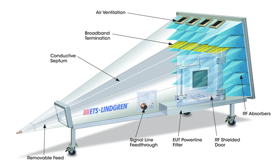
According to Vic Hudson, director EMC test solutions at ETS-Lindgren, the company “can offer the test environment best suited to the application, that is, a GTEM! (Figure 2), anechoic chamber, or reverb chamber, since we have decades of experience in the design, manufacture, and installation of these test environments.”
|
Figure 2. GTEM! Test Cell Courtesy of ETS-Lindgren
|
The company’s website claims design and installation of more than 10,000 RF chambers and enclosures worldwide. These range from 3-meter and 10-meter anechoic and semi-anechoic chambers to the less conventional GTEM! shielded enclosure. The successful installation of very large chambers requires considerable project management experience, which ETS-Lindgren also provides. In addition to chambers, products include the ferrite and molded absorbers used inside chambers to control reflections, many types of antennas, and related ancillary equipment.
On July 30, 2012, R&S took over the sales of anechoic chambers and shielded rooms from the Albatross Projects Group in the United States and Canada, and therefore production, sales, and service of complete EMC systems now are available from a single source. The two companies had globally collaborated for more than 20 years on turnkey solutions and EMC test systems.
Since its foundation in 1999, Albatross Projects expanded to become The Albatross Projects Group. According to the company’s website, this group of companies has become a leading supplier of absorber materials and test-chamber solutions to the RF shielding and EMC-microwave test markets. The website listed four application areas:
-
Electromagnetic Compatibility: for EMI and EMS measurements, including all necessary infrastructure accessories, customized design for radiated emission measurements, and radiated immunity testing to serve industrial electronics, telecommunication, automotive, metrology, and test houses.
-
Microwave: chambers to determine the antenna characteristics and design of antennas including all necessary infrastructure accessories and customized design for applications such as antenna pattern, radar cross section, electronic warfare, and near-field test range.
-
Medical/Magnetic Resonance Imaging: MRI shielding, MRI accessories, MRI testing, and MRI services.
-
Defense/Government: shielded computer rooms, shielded conference rooms, and shielded C³ operation centers.
EMC Software
RadiMation is a comprehensive EMC software application from D.A.R.E!! Instruments that automates immunity and emission testing and report generation. More than 3,000 instrument drivers are available, and the company will write new ones if required.
As detailed on the company’s website, RadiMation supports civil, automotive, military, and aerospace standards, and the test results can easily be exported. All modules have the same look and feel, which reduce learning time. Finally, often-used tests can be stored in a technical setup file that directly relates to the applicable standard. Recalling the stored test rather than re-entering data increases throughput and reduces errors.
ETS-Lindgren’s TILE! (totally integrated lab environment) EMC software features a graphical interface that makes it easy to create test profiles. A test consists of the steps represented by a connected string of icons. The six icon types are emissions, immunity, information, utility, GTEM, and miscellaneous. Icons are customized by right-clicking on the symbol, which opens a dialog box. More than 1,600 drivers are available.
According to the datasheet, “TILE! offers the capability to create as many graphs and tables as needed. Parameters for the graphs and tables are defined by the user and updated and displayed in real time as the data is collected. Graphs can be exported as Windows metafiles (.wmf), and tables can be exported as comma-separated files (.csv) for use in tools like Microsoft Excel to generate test reports.”
R&S also has specialized EMC test software, as described by the company’s Zavodny. “ES-SCAN is a cost-efficient software application for EMI test receivers and spectrum analyzers. The main requirements of EMI measurements in accordance with commercial standards have been combined in an easy-to-use application: measurement settings and storage, scan data acquisition and display with automatic data reduction, peak search with acceptance limit and selection of subranges, final measurement with worst-case selection, report generation, and measurement data storage.
“[Alternatively,] the EMC32 EMC measurement software can be used for all EMI and EMS measurements. The software is a tool for controlling and monitoring Rohde & Schwarz devices as well as third-party equipment.” Zavodny concluded, “Thanks to its comprehensive and modular configuration capabilities and its open software structure, it ensures reliable collection, evaluation, and documentation of measurement results.”
Integrated EMC Test Systems
D.A.R.E!!’s Radicenter chassis offer one, two, or seven slots to house a range of EMC instruments. General Manager René Dijkstra listed several types of plug-in cards from which a complete EMC test system can be built:
-
RadiSense plug-in card to facilitate the complete range of RadiSense E-field sensors from 9 kHz to 18 GHz.
-
The RadiPower plug-in card to facilitate the complete range of RadiPower EMC/RF power meters from 9 kHz to 18 GHz up to 1 MS/s.
-
RadiSwitch plug-in cards, a complete range of switch cards with BNC, N-type, SMA, and K-type connectors from DC to 40 GHz.
-
The RadiGen EMC/RF signal generator from 9 kHz to 6 GHz.
The overall system can be automated by RadiMation EMC test software. RadiControl software controls EMC antenna masts and turntables.
EMIPAK from R&S is centered on FCC/CISPR/EN type radiated emissions. According to Zavodny, “It includes key components to enable EMI tests on any R&S spectrum analyzer or test receiver. A compact biconical/log periodic antenna that covers the critical frequency range of 30 MHz to 3 GHz is central to the kit. Also included is a near-field probe kit for analyzing shields, chips, traces, and circuit boards to localize emission sources. A high-quality RF cable, low noise preamplifier, and tripod for mounting the antenna round out the basic kit. As an option to the base kit, a line impedance stabilization network also is offered for conducted emissions.”
Rather than offer a specific test system, Agilent has partnered with a number of companies to provide a variety of EMC test solutions. One of these is the RCE EMI scanner that combines E-field and H-field probes and a camera available from Eretec. Emissions from an active PCB are measured by an Agilent spectrum analyzer and correlated to the camera’s view of the components being scanned.
ETS-Lindgren also is an Agilent Solutions Partner. As described in a document highlighting the benefits of both company’s products, “When integrated with EMC chambers, antennas, towers, turntables, and test accessories from ETS-Lindgren, TILE! and the MXE support the foundation of a comprehensive EMC test system. Together TILE! and the new Agilent MXE EMI receiver provide EMC labs a flexible, integrated solution to ensure the compliance of products to international standards such as CISPR both today and tomorrow.”
ETS-Lindgren also offers the EMCenter test system to complement the company’s other products. As explained by ETS-Lindgren Global Marcom Director Glen Watkins, “We can integrate almost anyone’s instrumentation into our system, and we support all test environments—anechoic chambers, reverb rooms, GTEM’s, test cells, and OATS. This frees us from selling a particular system based on proprietary elements. Our customers can select the best solution for their requirements rather than us telling them what we think they should buy.”
Although TDK RF Solutions offers chamber and test-system design capabilities, a line from the company’s Integrated Test Systems brochure gives a good idea of the TDK focus: “At TDK RF Solutions, our area of specialization is integrated system design.” So, rather than include TDK in the chamber or software sections, placing more emphasis on complete turnkey solutions seemed more appropriate. The company provides industry-specific solutions for automotive, telecommunications, military, and aerospace EMC compliance testing.
EMC Moving Forward
Spelling electromagnetic compatibility in full helps to emphasize the importance of compatibility. Especially when an application contains both high and low power elements, it’s important that all the parts play well together.
As examples, Agilent’s Terrien said, “…two major forces are driving the development of new EMC test capabilities and methods. First, the growing numbers of electric and hybrid vehicles along with the adoption of electronic content in traditional vehicles have caused PCs and LANs to be coupled with electronic power and drive control systems.” He concluded, “Second, smart power grids have introduced millions of transmitters to monitor and control utility resources.”
|